

The aluminum foundry industry has learned the hard way that the world is flat. The last 40 years have seen the global industry grow while the domestic industry has contracted. Like other industries, foundries must constantly be on the lookout for new ways to boost productivity, cut costs, and increase quality. A focused work cell using industrial automation is one of the tools for accomplishing this goal, but in most cases simply installing a robot to tend an existing casting machine is not a suitable solution.
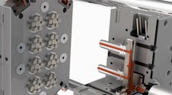
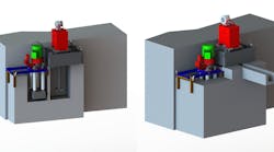
Conventional tilt-pour casting machines have frames or tie bars that can hinder robot interaction with the machine. Machinery designers have long felt that the die should be clamped in a “box” making tie bars necessary in a C-frame style machine. CMH Manufacturing believed there had to be a better way and began to design a series of tilt-pour casting machines that do not use tie bars. The development started with the Hall 3HS, the most popular tilt-pour casting machine in the domestic foundry market, resulting in the 3R. The 3R is the same size as the 3HS but has no tie bars to hinder the robot interaction. Possible robot functions in the cell include: Core placement in semi-permanent mold casting; ladling; casting extraction; post-extraction processing; and inspection.
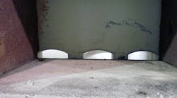
We started the design process by modeling the 3HS machine and running a finite-element analysis to determine the stress points on the machine with the tie bars in place. To confirm the design we clamped a 21x21x21-in. block in a 3HS in three different positions on the Y-axis of the platen, the block at the top of the platen, middle of the platen and the bottom of the platen. The X-axis was centered in all three situations.
Using a FARO arm 3D measuring device and a laser scanning head, we measured the platen deformation at two different clamping forces: 50,268 lb. and 60,322 lb. of clamping force. The finite-element analysis and the laser scan both showed the same basic machine deformation.
The graphic illustration drawn from the finite element analysis illustrates the maximum and minimum platen deflection:
Based on the knowledge gleaned from testing the 3HS we were able to eliminate the tie bars by converting the flat-sided C-frame to an I-beam at the front. We converted the rear of the machine and the ram cylinder mount into a reinforced box. Corner stiffeners were added in eight places. The movable platen was converted from two inches thick to three inches thick. In order to give more balanced clamping force we converted from the two 5-in. ram cylinders (39.28 sq. in. cross sectional area) to four 4-in. ram cylinders (50.28 sq. in. cross sectional area.) The increased clamping force means that the pump pressure can be reduced, improving pump life. Another design improvement was to adopt high-performance linear ball bearing way bars. Using exactly the same testing procedure described above we scanned the 3R machine, with the following results (deflection in inches):

As shown, the front platen on the 3HS deflected 0.058 in. compared to 0.0315 in. on the 3R, a 47% improvement. The 3HS rear platen deflected 0.048 in. compared to 0.0395 in. on the 3R, an 18% improvement. The 3HS movable platen deflected 0.017 in. while the 3R deflected 0.001 in., a 94% improvement.
With the success of the 3R, CMH quickly developed the 6R, which can operate dies 60x60 in. and weighs 13,000 lb. The addition of the 6R gives CMH Manufacturing the ability to offer permanent mold foundries three sizes of machines without tie bars.
The Advantage of a Robotic Work Cell
Why develop these machines? What is the advantage of a focused robotic work cell in a permanent mold foundry?
A focused work cell in the foundry is the logical and strategic arrangement of resources, organized so to improve process flow, increase efficiency and eliminate muda (waste.) These principles are based on the concepts of Lean manufacturing.
Work cells appear simple, but beneath this simplicity is a sophisticated engineering project. Like any other engineering design, it proceeds through a logical sequence of steps. At each step, the designers make compromises between conflicting requirements or technical limitations.
The steps required are:
• Select the product,
• Engineer the process,
• Define the infrastructure, and
• Layout the work cell.
A focused work cell in a tilt-pour operation can offer advantages in material handling, inventory, quality, scheduling, personnel, and customer satisfaction. These advantages are a result of the focused work cell’s small size and process integration. Worker satisfaction may be higher because of the human natural desire to work in small groups.
There is a marketing benefit, too. The customer sees improved quality and faster response to special request and delivery. A focused work cell allows permanent mold foundries to deliver small quantities reliably without the foundry or the customer having to hold large inventories.
CMH Manufacturing Co. recognizes that metalcasting facilities are expensive and their service life is measured in years and decades. With its own designs, and automation equipment supplied by partners Kuka Robotics and Fanuc Robotics, it will provide decades of insight and experience in permanent mold focused work cell design.
John Hall is the president of CMH Manufacturing Co. Visit www.cmhmfg.com for more information.