


 – which several automotive foundries have implemented already – is an inspection process that supports wider digitalization efforts, optimizing product design and production planning.")

If your work involves managing a metalcasting operation you probably view casting simulation software as a tool – on object, to use to get the results you seek within the process you undertake, pouring metal to achieve finished parts. In fact, it is a tool to be used for that reason.
If your work is developing casting simulation software though, you probably view these programs as products —discrete outputs of a specific but expansive sphere of knowledge, with numerous applications and innumerable other iterations. Indeed, casting simulation is that precisely.
But, another aspect of casting simulation software may be seen from what results from the collaboration of developers and users. If you watch how they define and apply these programs you’ll quickly discern the issues guiding decision-making and strategy in metalcasting today. And, each new program release reveals something new about where the industry is heading.
Simulation software refers to programs within the broader category of process modeling software, which uses numerical analysis and data structures to analyze and resolve problems. To the developers, their science is “computational fluid dynamics,” so called because all that numerical and data analysis is being used simulate the interactions of materials and forces — e.g., liquids and gases as they fill a mold and take a solid form. The simulations may be hypothetical or practical, and they make it possible to predict the outcome of a production sequence in terms of manufacturing cost and time and product quality.
Late last month, Flow Science, Inc. released version 5.0 of its metalcasting simulation software, FLOW-3D CAST. It introduces utilities that users can apply to predict casting defects, so as to shorten design cycles and cut production costs. That much is to be expected.
But, FLOW-3D CAST v5 is also decidedly more focused on particular problem-solving sequences, to the extent that it’s arranged in suites according to the type of casting to be simulated — e.g., permanent mold casting, high-pressure diecasting, sand casting — making the presentation highly recognizable to users and the set-up and simulation faster and more intuitive.
“FLOW-3D CAST has never been a ‘black box,’ and user flexibility is an important component of that,” explained Dr. Amir Isfahani, president & CEO of Flow Science, Inc. “The challenge is designing a software that is simple on the face of it but highly flexible for expert users of, for example, an R&D team at a major automotive company. FLOW-3D CAST does a great job of showing only what the user needs while maintaining accessibility of advanced options that provide a plethora of flexibilities subtly tucked away.”
Set-up and go — Process-driven workspaces were introduced in an earlier version of FLOW-3D CAST, and now have been expanded to include permanent mold processes, such as gravity diecasting, low-pressure diecasting, tilt-pour casting; and sand casting processes like gravity sand casting, low-pressure sand casting, and lost foam casting. (Other process workspaces, e.g., investment casting, sand coremaking, and centrifugal casting, are in development.)
For the users of FLOW-3D CAST v5, the flexibility provided by the different suites is twinned with an increasingly simplified set-up sequence. Once a preferred suite is selected, the software provides the appropriate process parameters, geometry types, and defaults.
For example, the Permanent Mold Suite includes process workspaces for gravity diecasting, low-pressure diecasting, as well as tilt-pour casting. The other suites offer additional, specific process types, and for each process the user interface displays only what is relevant to that particular process.
Also, users can expand the simulation process to include steps like transferring and filling a ladle, from the melt pool to the shot sleeve or pour cup. For low-pressure diecasting, the process engineer can model the pressurization of the crucible and the flow of metal into the mold.
Making simulation software simpler for users to run supports their time- and cost-management efforts. “What we have accomplished with FLOW-3D CAST is to build-in expert knowledge from the metalcasting industry, which comes from our customers and in-house know-how over the past four decades,” Isfahani commented.
Users taking advantage of the simplicity and speed in the new version of FLOW-3D CAST will also gain a greater sense of its versatility. “This extends the modeling possibilities beyond just filling the mold and solidification,” he added, referring to program’s ability to model scooping the metal with the ladle and then movement of the ladle before and during a pour. “FLOW-3D CAST is the sister product of a highly sophisticated, general CFD tool and has access to many advanced multi-physics capabilities that other dedicated metal casting software might not.”
Defect prediction — The simplicity or versatility of a simulation program is only valuable if the technology is effective. “Process-driven workspaces mimic the actual workflow of our customers on the shop floor. At the same time within these processes and across the industry, defect prediction is key to optimizing designs and getting the best product to market,” the Flow Science executive clarified. “And of course, these defects and their classification differ from process to process, especially when the physics involved are wildly different.”
FLOW-3D CAST v5 introduces a series of new tools for identifying defects and predicting their development, including void particles to locate filling defects caused by entrapped gas. In previous programs, collapsed gas regions would disappear from simulation if they became too compressed to be resolved in the numerical mesh. Void particles change size in response to the surrounding metal pressure, and their location at the end of filling indicates a potential defect due to air entrainment and/or oxides.
Wall contact time helps identify locations on the mold surface that have been exposed to metal longer than others, and so may be more susceptible to erosion. Metal contact time reflects the amount of time metal has been in contact with sand or other solids, which may lead to microporosity.
With FLOW-3D CAST v5, the output for the metal contact time with individual solid components is extended to include the contact time with all components.
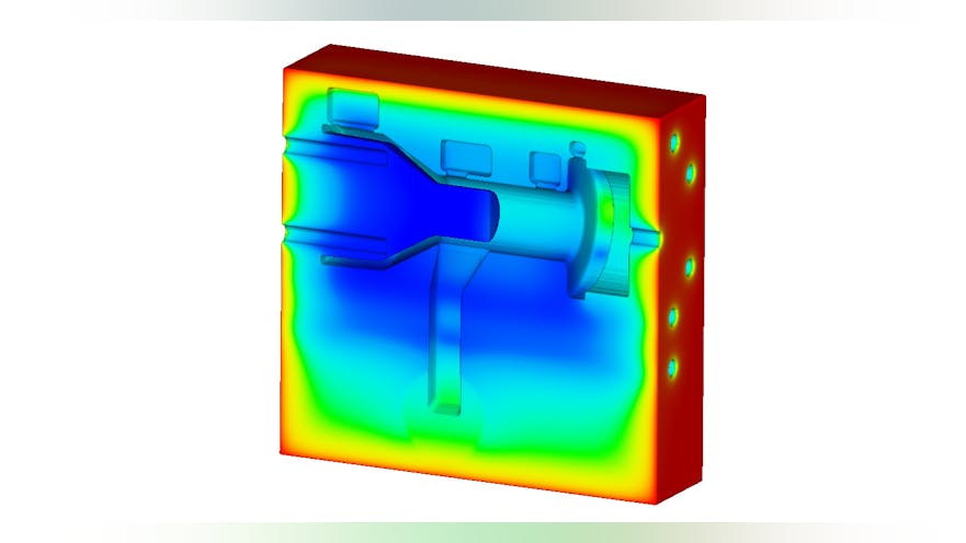
For identifying solidification defects, the Thermal Modulus that is commonly used for sizing risers is now output from solidification simulations.
Another new output quantity, Hot Spots, can be used in mold design to locate and size risers and identify potential solidification-related defects. Hot spots indicate the last places to solidify, and are represented by particles and colored by hot spot magnitude. Risers can be located where the hot spot magnitude is greatest.
A new Porosity Analysis Tool identifies porosity-related defects in real-world terms. Defects can be identified by their net volume, largest linear extent, shape factor, and total count.
Feedback loop — The new availability of such functions underscores the point that casting simulation programs represent the steady progress of science and technology, as well as the economic and performance objectives of individual metalcasters. Values like flexibility, versatility, and functionality are as relevant in science as they are in commerce, and as important to producing castings as to developing new software.
“FLOW-3D provides solutions to a wide spectrum of industries, from civil and environmental to aerospace and biotech and in our experience, metalcasting process simulations are some of the most complex and challenging simulations in the CFD domain,” Dr. Isfahani explained.
Another way of looking at this is that the software users’ experience and needs are guiding much of the research that leads to new functionalities, as in FLOW-3D CAST v5.
This user input is not confined to functionality. Amir Isfahani added that interface design and development comprise an even tighter “feedback loop” for software developers.
As for the direction of metalcasting and simulation software, the loop seems likely to get tighter. As the software users seek more answers to perfect their production processes, they will become more invested in the design of the products and the quality of their results. As the software developers seek more understanding of the potential for their technology, they will rely more on the real-world effects of simulating metalcasting processes.

 and fluid (green) patterns that illustrate the impact of the bias field that the researchers indicate guides solidification in metals.")