Making Product Design More Reliable for Process Modeling
For metalcasters, the critical value of casting process simulation is to identify the flaws in a production sequence – the dimensions of a mold or core, or the gating or venting concept, or the pouring method, or some other factor that is not apparent from a CAD design or prototype. Only the simulation reveals the process.
Computational fluid dynamics is the basis of most casting process simulation: CFD corrals all the relevant factors and evaluates the theoretical results of a production process. The role of these programs in the metalcasting industry cannot be exaggerated – and with the emergence of more powerful computing the influence will increase.
But, before a casting process is simulated a casting must be modeled, and before that it must be designed. Finite-element modeling is a basic function of product design, and for producers of castings the results of FEM are becoming as important as CFD. FEM identifies for casting designers how a conceptual product will react to actual expected conditions (the heat or pressure of an engine, for example), and can indicate where that conceptual design is likely to weaken or fail.
Automotive casting group Federal-Mogul Powertrain recently developed a simplified transient dynamic simulation model for the closing action of an engine valve, in order to predict the effect of dynamic loads on valves in operation. By improving the accuracy of its deformation and stress calculations, Federal-Mogul indicated it’s able to estimate valve fatigue life more reliably. This helps to optimize material selection for valves, and contributes to the broader effort to improve engine design and performance.
“The dynamic loading during valve closing is a decisive factor in designing intake and exhaust valves,” explained Federal-Mogul Powertrain CTO Gian Maria Olivetti. “With the new simulation method, we can quickly calculate the maximum expected valve loads, thus saving time and ensuring targeted development.”
In design of intake and exhaust valves for combustion engines — especially the emerging class of fuel-efficient engines developed with a high degree of forced induction, e.g., by supercharging or turbocharging — loading conditions during valve closing is a significant focus of product design, and a particular design problem.
The design of valve drive systems very often is still in development as the valves themselves are being designed for new engine projects. This constrains the metalcasters that will produce the valves from planning a fully optimized production process. Thus, the valve designers must rely on simplified simulation models that limit valve loading evaluation to the main parameters, for example, valve closing speed, valve spring return force and the clearance between valve stem and guide. The challenge to the valve designer is to optimize the product design to the extent that the production process designers can approach their task without returning the entire program to the drawing board.
During valve closing, one side of the valve usually contacts the valve seat first, which can introduce heavy loading of the valve stem. The dynamic simulation model of the closing event developed by Federal-Mogul makes it possible for the casting designer to calculate those loads with a high degree of certainty. In turn, that allows parts to be configured optimally from the initial design stage, and for the manufacturing process to be optimized in turn. For a supplier like Federal-Mogul, it also means that the cast products’ life span can be determined with even higher accuracy.
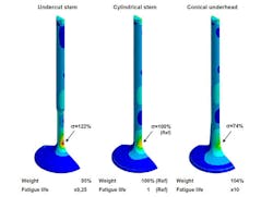
In addition to fatigue life, the load values associated with valve closing determined by way of FEM sequences also can be used to evaluate and rank alternative valve designs, according to Dr. Guido Bayard, Federal-Mogul Powertrain’s director for Valve Technology.
“Different detail geometry, such as a stem undercut or conical underhead, has a major influence on the stress distribution,” according to Bayard. “With our simplified FEM simulation, we can quickly draw conclusions on maximum valve loading and likely fatigue failure, and make sound decisions on design and material at an early stage of development.”
The results derived using the simulation model have been confirmed by practical testing on a valve test rig developed by Federal-Mogul Powertrain that makes it possible to demonstrate the performance action of an individual valve, and thus to evaluate individual closing events. The rig is better suited for validating a simulation model than a complete cylinder head for a number of reasons: it provides greater flexibility in the geometry that can be tested, and it offers better controllability of measurements and improved access for measurement technology.
About the Author
Robert Brooks
Content Director
Robert Brooks has been a business-to-business reporter, writer, editor, and columnist for more than 20 years, specializing in the primary metal and basic manufacturing industries. His work has covered a wide range of topics, including process technology, resource development, material selection, product design, workforce development, and industrial market strategies, among others.

