Economic Consequences of Insoluble Buildup on Coreless Melting Efficiency
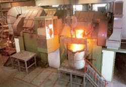
A coreless induction furnace is essentially a refractory-lined vessel surrounded by an electrically energized, current-carrying, water-cooled copper coil. Electrical current in the coil induces an electromagnetic field, which magnetically "couples" with the magnetic charge, producing electrical current within the charge itself. Each piece of metallic charge has its own internal resistance that, when energized by these internal currents, will heat up and eventually melt. The resulting magnetic field in the molten metal causes a stirring action, thus ensuring a homogenous liquid mass.
In all coreless induction furnaces, there is an “ideal” refractory wall thickness, carefully calculated by the furnace manufacturers for optimal melting performance. This calculation includes safety considerations, electrical characteristics of the coil, metallic charge resistance / electrical conductivity, structural and refractory considerations, operational constraints and production needs. When the furnace melt diameter is reduced by buildup, the melting process efficiency becomes compromised. The result is a reduction in the percent power utilization and energy consumption increases.
The cleanliness of the metallic charge (often consisting of sand-encrusted gates and risers, or rust- and dirt-encrusted scrap) significantly affects the type of slag formed during melting. In a coreless induction furnace, slag residuals normally deposit along the refractory walls within or slightly above the active power coil. Because these oxides and nonmetallics are not soluble in molten metal, they float in the liquid metal as an emulsion. When flotation effects become great enough, nonmetallics rise to the surface of the molten metal and agglomerate as a slag. Once the nonmetallics coalesce into a floating mass on the liquid metal they can be removed. The use of a suitable flux greatly accelerates this flotation process.
When slag makes contact with an area of the refractory wall that is colder than the melting point of the slag, the cooling slag will adhere to the lining. That adhering material is called buildup. High melting point slags are especially prone to promoting buildup. If not prevented from forming or not removed early during formation, buildup will reduce the overall efficiency and capacity of the furnace.
The mineral composition of the refractory lining for melting iron will almost invariably be silica. Silica constitutes a compromise between good thermal insulation, adequate mechanical impact strength to protect the coil, and good thermal shock resistance during a batch melting process.
Decreasing refractory wall thickness in a coreless furnace improves the coil efficiency and increases the effective power input. Studies have shown a substantial reduction in power consumption with decreasing thickness of the refractory lining.(1) With increasing furnace operating time and progressive refractory wear, power consumption decreased by 9% three weeks after a new lining was installed on a three-metric ton coreless furnace.
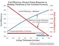
Conversely, the accumulation of insoluble slag buildup on the refractory wall will have the exact opposite effect. Not only will buildup increase the effective refractory wall thickness, but coil efficiency will decrease, as shown in Figure 1.(2) As the effective refractory thickness increases from slag buildup, coil efficiency decreases and the amount of electrical energy required to melt increases (shown as the approximated percentage of rated power.) The coil efficiency at the optimal lining thickness is 82% and the percentage of rated power in kilowatts (kWs) is 100%. As the buildup thickness approaches 2.5 inches, it is estimated that an additional 25% increase in kWs will be required to melt.
A thicker effective refractory lining equates to the metal bath being further away from the coil. This results in a lower coil-power factor and lower coil efficiency that produces higher current and greater electrical losses. Insoluble slag buildup has the same effect as increasing refractory thickness. Since there are more electrical losses in the coil, there is less energy available to melt metal, so every melt will take somewhat longer than it would with a standard refractory thickness. This can cause increased conductive and radiated heat losses, increasing the amount of energy consumed even further. Adding to this, the overall capacity of the furnace will decrease, reducing its output.(3)
Controlling buildup allows for more efficient furnace operation. Buildup can be controlled or eliminated by continuous addition of fluxes. Note that in the past the use of fluxes in ferrous foundries has been widely discouraged by refractory companies, but new developments in flux chemistry (Redux, U.S. Patent 7,68,473) allow for flux use in furnaces lined with dry vibratable silica refractories, without refractory attack.
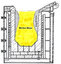
Generally, adding fluxes ensures that slags have a melting point below the coldest temperature in the system. Fluxes can help control slag and other insolubles from freezing on the cooler refractory surfaces. Adding flux allows for the flotation of the emulsified oxides and sulfides; it also may reduce the melting point of the slag to below the lowest temperature encountered in the melting furnace and associated liquid metal handling system. An example of severe buildup in a coreless furnace is shown in Figure 2.
Improper use of fluxes can lead to rapid erosion of furnace linings, especially if potent fluorspar-based fluxes are used. However, if a flux is carefully engineered for specific applications and used properly, refractory life actually may increase. Eliminating buildup optimizes power utilization, thereby reducing energy consumption.
The following example illustrates how flux additions can improve melting efficiency. Foundry G is a medium-sized gray-iron foundry. Historically it experienced extensive slag buildup on the upper sidewalls of its four three-ton medium-frequency coreless induction furnaces, in a semi-batch melting operation. With a newly installed silica lining, melting capacity is 1,525 tons/month with two furnaces running five days/week, 21 days/month.
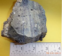
Foundry G’s charge consisted of 100% metallic fines and machining chips. Each coreless furnace is lined with a silica-based dry vibratable refractory. During melting, slag generation and residual buildup immediately reduced furnace capacity and contributed to increased melting time and increased power consumption. After 48 hours of operation, three inches of an iron oxide, silicate-rich buildup occurred along the entire sidewall (see Figure 3.)
Foundry G initially incorporated two pounds of Redux EF40L flux per ton of metallic charge, added to each back-charge to determine its effect on buildup. EF40L was added to the furnace before back-charging on top of existing molten metal to ensure excellent mixing, (a minimum 50% molten metal bath.) Immediate improvements were observed and buildup along the sidewalls essentially was eliminated. Because optimal refractory thickness was maintained, it is estimated that the power utilization increased by 25% compared to pre-buildup days.
Energy savings are estimated to approach $14.4K/month or $174K/year based on electrical usage of 550 kW/ton and an electrical rate of $0.069/kW, resulting from the percentage of rated power reduced by 25% (125% with buildup compared to 100% with no buildup.)
Foundry G observed the following after adopting Redux on a continuous basis:
• Reduced potential charging hang up/bridging issues due to cleaner refractory walls
• Reduced power consumption during each melt
• Less hourly maintenance for scraping
• Consistent furnace capacities: Furnace capacity was reduced by 0.95 tons (28.7%) when slag had built up to three inches thick
• Improved “electrical coupling” with improved temperature control
• No adverse effects on the dry vibratable silica refractory linings
• Estimated electrical savings of $174,000 annually.
In sum, insoluble buildup and slag-related problems have become serious issues for today’s foundry operations. These problems will likely only increase as the quality of scrap continues to deteriorate. However, using Redux fluxes properly can alleviate these challenges while increasing melting efficiency and saving foundries time and electricity, and improving profitability.
Rod Naro is president and CEO, and David C. Williams is v.p. - Technology of ASI International Ltd. Visit www.asi-alloys.com
Pete Satre is the manager of technical services for Allied Mineral Products Inc.
References
1. "Efficient melting in coreless induction furnaces," GOOD PRACTICE GUIDE No. 50, ETSU, Harwell, Didcot, Oxfordshire, 2000
2. Percentage of rated power approximated by authors based on review of the technical literature and discussions with coreless induction experts.
3. Dimensions of the refractory installation for a three-ton coreless induction furnace.