Advancing Inline Quality Control for Castings
For tiny cracks, pores, or other surface defects in castings that are hard to detect by the human eye, fluorescent dye penetrant testing is a well-established and widely applied inspection technique for both ferrous and nonferrous parts. “Mixed-light inspection” takes the quality-control pursuit several steps further, aiming to detect the very small levels of light emitted from fluorescent penetrant dyes against a background of strong daylight or other brightly lit environment.
However, the effectiveness of this inspection method currently depends upon the ambient lighting conditions being acceptably low (as specified in ASTM E709 and ASTM E1209, for example), which often limits its deployment to being used in darkened conditions indoors or under specially constructed, covered awnings and tents while working outdoors in daylight conditions or direct sunlight. This limits certain NDT inspection operations and makes others impossible altogether.
Furthermore, for inline inspection in a continuous production environment, the extra time and resources necessary to operate under low-light conditions can cause serious production bottlenecks, and it is expensive in terms of the manpower.
Inspection Technologies Ltd. has developed a mixed-light system that eliminates these production bottlenecks and significantly increases throughput rates at inline inspection points. The system includes software that completely automates the inspection process, hence removing the need for expensive highly qualified inspectors. After the automated inspection process is complete, visual photographic records of all inspections, either "pass" or "fail," are permanently stored for compliance and 100% Quality Audit purposes.
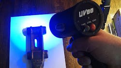
This mixed-light system (patent application #GB1610988.6, see Fig. 1) is comprised of a specialized camera, patented driver electronics and a self-contained UV light source. Advantageously, it allows for the effective detection of fluorescence, even in the presence of high levels of background illumination. Further, it avoids the need for items to be moved indoors or covered with tents or awnings when performing non-destructive testing techniques using fluorescent dyes and completely avoids the need for dimly lit environments. Indeed, in performance trials the initial commercial installations of this system have detected fluorescent radiation of 200 lux or lower, in the presence of background illumination of over 100,000 lux.
For most common NDT inspections via fluorescent techniques, the excitation source is an ultraviolet (UV) light-emitting diodes (LEDs) radiation source. When, for example, the fluorescent material of interest is a fluorophore, such as the commercially available Magnaflux® 14-HF (or similar) or Magnaflux® ZL-60C, as for use in fluorescent magnetic particle inspection (FMPI) and penetrant inspection (PI), then a suitable range of wavelengths for excitation radiation for such materials is 350 to 450 nm.
In addition to optical techniques, the system also employs digital signal processing (DSP)-assisted noise reduction, filtering, and contrast enhancement methods, in order to provide a clearer difference image in which any detected fluorescence can be seen more easily.
The final image, which eliminates all background light and is shown in real-time, thus allows the user to identify visually an area in which the fluorescent material is present as a continuous streaming video-feed. Such an arrangement is advantageous in an NDT process, where the fluorescence corresponding to a crack or other defect can de detected as part of a dynamic or moving inspection process (such as walking while inspecting) or for static in-line inspection of objects on a moving conveyor belt in a production setting.
The user interface for the system also contains automatic defect detection software that will identify and size areas of interest and alert the user. Optionally, the software can provide streaming, real-time visual overlays of these regions of fluorescence and identified defects, on top of ordinary visual images of the object under inspection.
Moreover, all captured images, regardless of whether they contain detected defects or other regions of interest, are permanently stored. This has several advantages in terms of compliance and insurance issues in that it effectively provides a truly 100% Quality Audit. Moreover, such an approach also makes it possible to assign technician-grade staff in lieu of more fully trained inspectors, and/or or that the productivity of a qualified inspector could be increased dramatically if he or she were able to inspect remotely via telemetry by supervising or reviewing the work of technicians on-site at multiple geographically separated sites.
Several industry-standard samples and test pieces were provided by Magnaflux® EMEAR. These were of a type that normally is used for quality assurance purposes on fluorescent magnetic particle dyes (used on ferrous metals) and fluorescent penetrant dyes (commonly used to detect defects associated with nonferrous metals). Figures 2 and 3 show the performance of the mixed-light apparatus on these samples under laboratory conditions.
Figure 4 shows a configuration of the mixed-light system in which the scanning head is attached to a robot arm, which then performs spot inspections at pre-set positions or in a continuous sweep of the surface. Visual records of all inspections are stored permenantly for compliance and Quality Assurance purposes.
Other useful aspects of the software are that as the precise positions of the defects are recorded, then it is also useful for process control, for example, if faults should occur more frequently in some locations as opposed to others.
Dr. Geoff Diamond is the chief technical officer for Inspection Technologies Ltd. Contact him at [email protected], or learn more at inspectiontechnologies.co.uk
