


Grede Foundries Inc. operates eight ferrous foundries (gray, ductile, and specialty iron, and stainless steel castings), and maintains a tool inventory that is among its most valuable resources.
At Grede’s foundry in Reedsburg, WI, gray iron is poured into sand molds to cast suspension parts, differential cases, crankshafts, and similar parts. The hundreds of patterns that create these molds are regularly checked by inspectors using a coordinate measuring machine (CMM) retrofitted with an LC50 laser scanner from Metris USA Inc. (www.metris.com). Their aim is to prevent the inevitable wear on the surface of the tool from advancing to the point where it may cause quality problems, and damage that is expensive to repair.
The LC50 is an industrial laser scanner for CMM applications that Metris reports will accurately capture 19,200 real points per second.
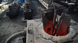
Patterns are essential to a foundry. The patterns create impressions in sand to form the mold into which molten steel is poured. The constant pushing of the pattern against the sand abrades the surface and wears away important details. To delay this wear, Grede protects the surfaces by applying hard, abrasion-resistant chromium based coatings chosen carefully for each job. In time though, the sand eventually wears them away, too.
“After a specified number of cycles or when the operator can see wear, a pattern has to be inspected,” states Bernie Bill, Grede’s layout supervisor in charge of the Quality Laboratory. “We will rescan it and compare the measurements to the baseline.”
The baseline is the scan of a pattern that has been proven to produce good castings. “We don’t compare measurements to the original CAD model of the part because the pattern has to vary from it slightly, to accommodate shrinkage,” says Bill. “We have to ‘tweak’ the pattern here and there to get the castings to meet customer specifications.” Once the patterns are able to make good castings and the customer approves them, Bill’s team scans the tool and stores the cloud of points as an STL file.
Checking patterns for wear is a fairly quick process. Although writing the macro for an inspection routine takes four to 16 hours, depending on the size and complexity of the pattern, the programming occurs during the approval process and is ready to use again. The inspector aligns the pattern to a jig mounted on the CMM, retrieves the program used to create the baseline STL model of the pattern, and lets the CMM inspect the tool. The inspection routine usually takes 30 minutes to an hour, depending on the pattern’s size and complexity. Some patterns contain several cavities to produce molds that can make half a dozen or more parts at once.
The next step involves Metris’ Focus Inspect software to compare the cloud of measurement points to the baseline and generate a color-coded map of the part. “You can have results within 15 minutes to half an hour,” Bill says. Because each color represents a deviation from nominal, production can see at a glance where wear is occurring, and how much has occurred.
“The results tell them what the plan for the pattern is going to be,” says Bill. “They know that they might be able to get by with running 5,000 more cycles before sending the tool out for stripping and recoating.” Or, they might immediately remove the tool from service, to prevent further wear that would require welding and grinding the tool to bring it back into specification.
If, however, they find that they are too late and that repairs are necessary, then the scanner checks the repairs afterward against the baseline, to ensure that they have returned the pattern to the approved specifications.
Monitoring wear is not the only use of the laser scanner and baseline scans. Scanning helps plant engineering to troubleshoot problems, either to add value to customer service, or to solve problems that randomly enter into any manufacturing process. “If production has a problem, they’ll often schedule a tool for a scan to rule out the tool before going to engineering,” says Bill.
For example, scanning may help them to diagnose an alignment problem that could prevent the two halves of the mold from fitting together. Without enough clearance, the two sandbanks on the outer edges of the two halves of the mold will crush each other, which may cause sand to fall into the cavity. Then, iron would solidify around the sand, creating porosity in the casting.
The alternate problem happens when there is too much clearance between the mold halves, allowing molten metal to exit at the parting line. This results in flashing that must be cut and ground away from the finished casting — adding to production cost and time.
“So we scan both patterns, put the scans together, and check for clearance and crush electronically,” says Bill. “When we put it on the screen, we can see whether it’s a pattern problem and, if it is, exactly what they’ve got to fix.” Not only do the color maps eliminate the need to pour over tables of measurement data, but they also can be attached to work orders to show the problem clearly to toolmakers in the pattern shop.
In the past, the toolmakers had to weld and grind the patterns based upon their experience and those tables of measurements, which were taken by touch probe from a sample casting. Then, the operators would have to interrupt production on a molding machine to install the repaired pattern and produce another sample for inspection. With laser scanning, however, diagnosing problems and repairing patterns is no longer a trial-and-error process. Because scanning collects more data in less time and presents it in a format that can be read intuitively, it eliminates guesswork. “It may be erasing three to five samples,” says Bill, “which means eliminating three to four shifts of work in the pattern shop, production, and inspection to make the necessary adjustments.” Most of the time now, the pattern shop is making the right correction the first time on the first try.
Moreover, scrap rates are down significantly. A good example is a set of tools for making a bracket for automotive brakes. Laser scanning helped Grede engineers to find some clearance in the patterns, as well as some variation in the machine that exacerbated the problem and created a lot of scrap. Based on information drawn from the color maps, tooling engineers were able to reduce a 5.2% scrap rate to 1.0%, saving $48,000 a year on one job.
Although Grede’s savings from eliminating trial and error is impossible to calculate, the savings from reducing the scrap rates is known. After using the scanner for six months, Bill estimated that using it for just one shift per day would save the company about $81,000 during the first year by reducing scrap – and that figure includes the cost of the Metris laser scanner and software. Almost six months later, he reportedly had to revise his estimate upward. The current plan is to play it even smarter – to scale up and run the scanner through another shift.